| JEPPO TOWER |
|
|
The radio really caught my eye at first sight.
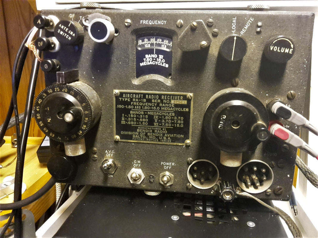
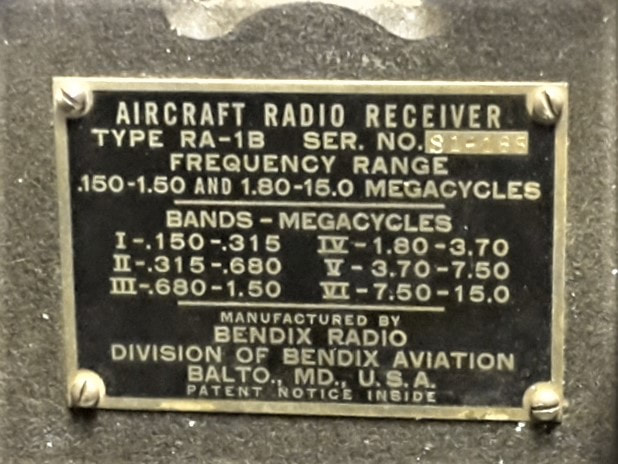
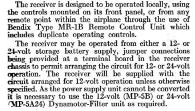
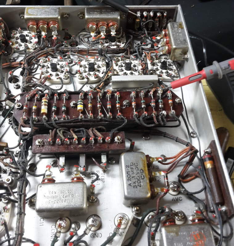
I was taking care of some old radio equipment after my friend and earlier neighbor Rolf, he was one of the radio club members of OH6AA that prepared a course together with the evening school in Vasa, to take us through the Radio armature licence test. The receiver is compact, the front is only 250mm x 180mm. We have 6 bands covering 0.150MHz to 15.0MHz as specified on the front plate of the receiver. The mechanical solution, how the nobs for the VFO and band switching worked, really made an impression on me. First idea was to keep it as a show item in my ham shack. At home, the case was opened, just to check out how the reduction gears for the VFO and band switching nobs were constructed. The parts inside of the radio looked promising, without any traces of overheating or electrical disasters, but with some extra wires in the circuits, clearly not from the 40s. With the radio came a pamphlet with specifications and schematics, printed and advertised by Electronic Precision Equipment LTD. Found on page 35 in Practical Television October 1956. Well, what would it take to get this radio to work? At least DC high / low voltages for the valves, and some type of adapter for the audio output. Lots of hits on the net when searching for RA-1B. BENDIX RA-1B Aircraft Receiver World Flight 1937 Radio type RA-1B World Flight research site |
|
I found that I had two options, a nice vintage radio item for display in my ham shack, or a working vintage receiver, displayed in my shack.
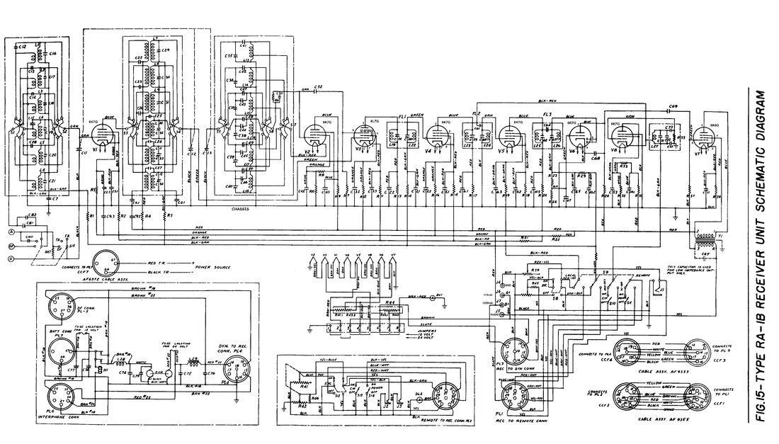
A good start is to check out what the net has to tell about this RA-1B Bendix receiver. Schematics, pictures and service instructions were easily found.
A good start is to check out what the net has to tell about this RA-1B Bendix receiver. Schematics, pictures and service instructions were easily found.
|
HV 220V and 12V DC for the heaters is suggested in the example that I downloaded.
Next was to build and test a power supply with these specifications. I had som vintage meters that would match the radio, and after some struggling with inrush currents to the supply, I had it working, 220VDC and 12VDC output. 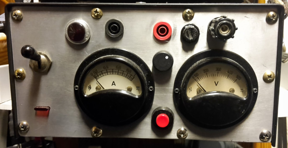
|
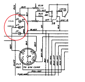
As I mentioned, some internal, and some external modifications have been made to the receiver. The power is now fed through the Test jacks 6 and 7, the potentiometer installed at the upper left corner, seems to be wired to the AVC function. The open connectors on the lower right side will bee covered, some of the pins are live 220V.
|
RA-1B is described in the service manual as a Superheterodyne design with an intermediet IF of 1630KHz. To receive CW, a 1631KHz beat oscillator output is fed to the IF, this will produce an audible beat frequency of 1KHz. This signal is amplified and fed to the audio output.
The audio output is designed for about 300Ohm, some type of transformer will be needed if 8-16Ohm standard headphones are used. A small transformer, 230V to 12V is wired with the 230 side to the audio output, and the 12 side wired to two stereo headphone jacks. One with the earpieces in parallell and the other with the ear pieces in series. Now was the time for the "fire test", 12V heater DC on, YES indicated current, then the HV 220V DC on - THEN NOTHING - VERY DISAPOINTING. Not even a smell of electrical activity, and the dial light just glowing. I left the radio alone for several weeks, and had my mind set to have a "dead" receiver as a show item in my shack. It bothered me, so just to calm my self, i started to read the service manual. On page 1 in section 1-1 the answer was found. This only emphasizes the old saying "Read the ***** manual". Yes, this receiver was "..otherwise specified..", with the jumpers set for 24V operation. After setting the jumper for 12V operation, the receiver came alive, now i had a working vintage receiver in my ham shack. |
Page 1 section 1-1
Jumper terminals 2-3 set for 24V
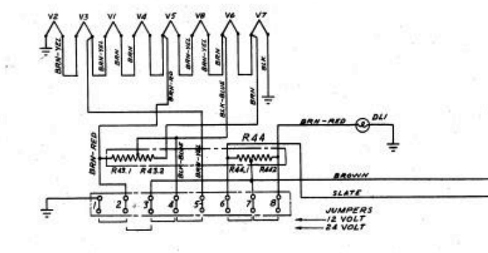
Settings for 12/24 Volts
|
RETURN to Radio
